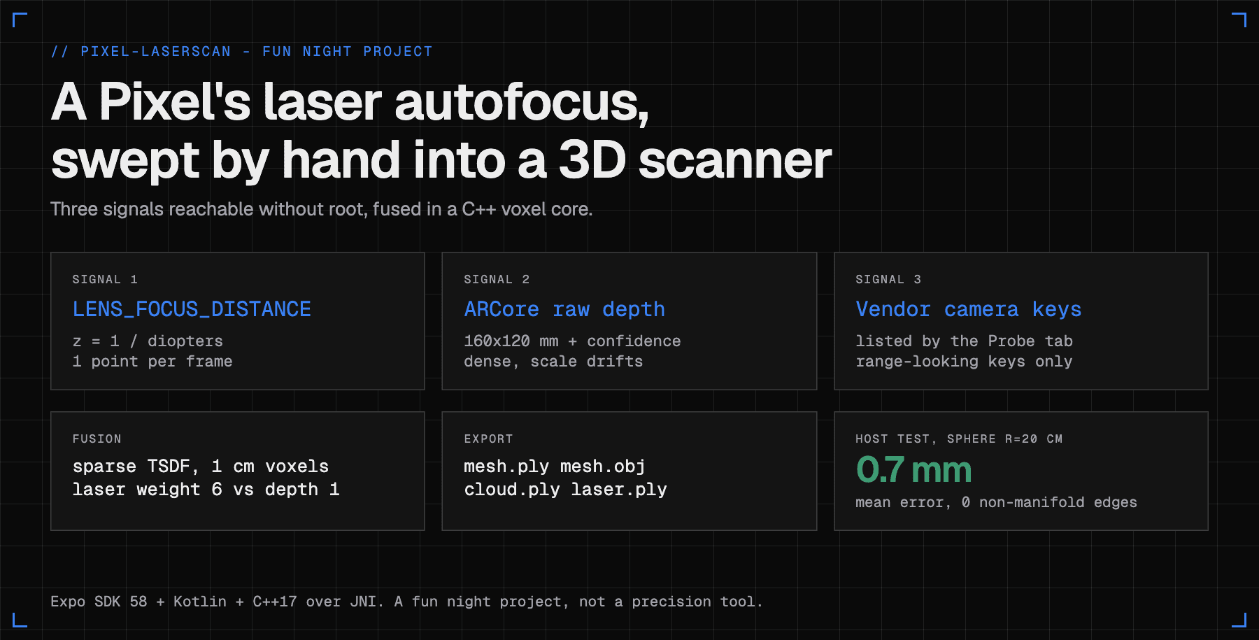
LaserScan is a small Android app I built that treats a Google Pixel's laser autofocus (LDAF) as a hand-swept, single-beam LiDAR. Android does not expose the sensor's zone grid (8x8 on Pixel Pro models, a single zone on the base models), so I used the three signals that are reachable without root: the LENS_FOCUS_DISTANCE value in every frame's metadata (z = 1 / diopters), vendor camera keys, and ARCore raw depth. Each laser reading has to pass about ten gates before it is trusted, including an agreement band against ARCore (0.7-1.4x on multi-zone phones, 0.8-1.25x on single-zone) and an edge check on the laser cone. Accepted hits are projected into world space with the ARCore pose and fused with ARCore depth in a sparse TSDF voxel volume written in C++17 over JNI (a laser hit weighs 6 depth rays on multi-zone phones). The core reconstructs a synthetic 20 cm sphere with 0.7 mm mean error in host tests, and the app exports mesh.ply, mesh.obj, cloud.ply and laser.ply. It is not a precision tool. I tested it by hand on my Pixel 10, but I have no tape-measure accuracy numbers to show you, and this post says so where it matters. It is a fun night project, and it runs on my Pixel 10.
Can a Pixel's laser autofocus work as a LiDAR?
I wanted to find out whether the laser autofocus on a Pixel could be used as a cheap range finder. Some Pixels have a small time-of-flight sensor next to the camera. It exists to help the lens focus. If it measures distance, and the phone knows where it is in space thanks to ARCore, then sweeping the phone across an object by hand should draw a line of 3D points. Do that long enough, add ARCore's dense depth, and you get a mesh.
The catch is that Android does not give apps the sensor. The camera driver (the HAL) eats the readings and hands the app a lens position. So this post is about how much of the laser you can recover from that lens position, how to keep the bad readings out, and what the whole pipeline looks like: React Native UI, a Kotlin module, a C++ fusion core.
Some framing first. The repo is vakharwalad23/pixel-laserscan, MIT licensed, and the README says it in the second paragraph: "It might not be the most accurate scanner out there, but it is a fun small night project." I agree with that sentence and wrote the code to match. Where something was measured I give the number. Where it was only checked on my Mac, or never measured, I say that.
Here is the plan for this post:
| Part | What you get |
|---|---|
| Autofocus from the ground up | contrast, phase detect, and laser time-of-flight |
| What a ToF sensor measures | a worked 1 m example and why timing is hard |
| The three reachable signals | focus distance in diopters, vendor keys, ARCore depth |
| Laser profiles and gating | per-model table and the rules a reading must pass |
| Fusion in C++ | pose, projection, weighting, outliers, mesh |
| App, export, tests, Docker | what the screens do and how I build it |
| What worked and what did not | honest list |
How does phone autofocus work, and where does a laser fit?
A phone has to move a lens to put the subject on the sensor sharply. It needs to know which way to move and how far. There are three common ways to find out.
Contrast detect. The phone moves the lens, measures how sharp the image is (edges get stronger when focus is right), and keeps going until sharpness peaks. It is a hill climb. It works anywhere there is contrast, but it has to overshoot to find the peak, so it is slow and it hunts.
Phase detect (PDAF). Some sensor pixels are split so that the left half and the right half look through opposite sides of the lens. When the image is out of focus, the left and right images are shifted relative to each other. The size and sign of the shift say how far and which way to move the lens. One look is enough, so it is fast. It still needs light and some texture, because it is comparing image content.
Laser (LDAF). A small emitter sends out infrared light and a detector measures how long it takes to come back. That is a distance measurement made with the phone's own light, so it does not care whether the room is dark or the wall is blank. That is why laser AF helps most in low light and low-contrast scenes, where contrast and phase detection struggle. Phones usually blend all three: the laser gives a quick first guess, PDAF refines it, contrast confirms.
That blending is the first problem for my idea. The number I can read later is not "what the laser said". It is "where the lens ended up", and the laser is one of the things that moved it.
Which Pixels have a laser?
The code in the repo carries a table keyed on the phone model. It follows Google's published specs as the README reads them. Google's store pages list a multi-zone LDAF (laser detect auto focus) sensor on the Pixel 10, 10 Pro and 10 Pro XL, and on the Pixel 11, which matches the multi-zone rows. I could not confirm the entries for the older models (Pixel 6 to 9, the Folds) from Google's pages, and I found no teardown naming the exact ST part inside any Pixel. So treat the part numbers below as the repo's claim, not as something verified on hardware.
- Pixel Pro models: described in the repo as an ST VL53L8, 8x8 multi-zone direct ToF.
- Base Pixels: described as an ST VL53L1, single zone.
The VL53L8CX itself, per ST, is an 8x8 multizone sensor with a 940 nm VCSEL emitter and a 65 degree diagonal field of view, and it can run as 16 or 64 zones (ST datasheet).
What does a direct time-of-flight sensor actually measure?
A direct ToF sensor measures one thing: the time between sending a pulse of light and seeing it come back. Distance follows from the speed of light.
d = c * t / 2 c = 299,792,458 m/s (the 2: out and back)
A worked example for a wall at exactly 1 m:
t = 2 * d / c = 2 * 1 m / 299,792,458 m/s = 6.67 ns
So the whole round trip takes about 6.7 nanoseconds. Now the hard part. To resolve 1 mm of range you have to resolve 2 mm of round-trip path:
dt = 2 * 0.001 m / 299,792,458 m/s = 6.67 ps
6.67 picoseconds is the period of a clock near 150 GHz. No phone runs a clock like that. Direct ToF sensors get there statistically. The detector is an array of single-photon avalanche diodes (SPADs), and the chip collects arrival times from many photons into a histogram. The peak of the histogram is the distance. Averaging makes the answer much finer than any single timestamp. I did not instrument any of this. It is the standard description of how these parts work, and it explains why a tiny module can range at all.
A multi-zone part does this for a grid of zones at once, each looking at a slightly different direction. That gives a small depth image, 8x8 pixels. A single-zone part gives one number for one fairly wide cone.
Why does Android hide the laser's zone grid?
Because the camera HAL owns the sensor. Autofocus runs inside the camera stack, below the Camera2 API. The HAL reads the ranging sensor, combines it with PDAF and contrast, and moves the lens. An app asking for the camera sees the result of that decision, not the raw zones. I found no public Android API that returns the zone grid, and the README states the same limit: "One focus distance per frame is the ceiling without root, and the HAL blends laser with PDAF to produce it."
That left me three things I could reach.
Signal 1: LENS_FOCUS_DISTANCE, in diopters
Every frame's capture result carries LENS_FOCUS_DISTANCE. Android defines the calibrated variants as "measured in diopters", and the uncalibrated one as "not accurate, and the units used for LENS_FOCUS_DISTANCE do not correspond to any physical units" (Camera2 reference). A diopter is 1 divided by meters, and 0 means infinity. On a phone with laser AF, the laser drives this value, so at the moment the lens stops, it is a distance to whatever the laser was pointing at.
The conversion is one division:
z = 1 / d

d = 2.0 diopters  ->  z = 0.50 m
d = 0.8 diopters  ->  z = 1.25 m
d = 0 diopters    ->  infinity (reject)
The cost is that the lens position is quantized in diopter steps, and the error grows with the square of distance:
dz = z^2 * dd        with a diopter error dd of 0.01
at 0.5 m:  0.25 * 0.01 = 2.5 mm
at 1.0 m:  1.00 * 0.01 = 1 cm
at 2.0 m:  4.00 * 0.01 = 4 cm
I should be clear that the 0.01 diopter figure is an example for the arithmetic, not a measured resolution of any Pixel. It shows the shape of the curve, and the shape is why the README says the focus distance gets coarse past about 1.5-2 m and rejects hits beyond 2.5 m.
Signal 2: vendor camera keys
Some makers publish extra metadata. The Probe tab dumps every capture-result key that is not in the android. namespace and whose name looks range-related, and lists sensors whose name or type contains words like tof, laser, vl53, range, distance, proximity or flight. It is a cheap fishing expedition. I will not claim it found a hidden zone grid, because the repo does not record that it did. It is a probe, and the result on a given phone is whatever that phone reports.
Signal 3: ARCore raw depth
ARCore gives a dense depth image (160x120 in the host tests, in millimeters) plus a per-pixel confidence value, computed from motion, not from any laser. It is plenty dense and it is metric-ish, but its scale can be off by a few percent and it is noisy. It also gives the thing the laser cannot: a camera pose every frame, a 4x4 matrix saying where the phone is and where it points. That pose is what lets a single-beam reading turn into a 3D point.
| LENS_FOCUS_DISTANCE | ARCore raw depth | |
|---|---|---|
| What it is | lens position driven by the laser | depth from motion (ML) |
| Coverage | one point per frame, image centre | a 160x120 grid |
| Strength | metric, good up close | dense |
| Weakness | coarse past about 1.5 m, blended with PDAF | noisy, scale bias |
| Needs | lens to settle and AF to report focused | features to track |
How does the app decide which Pixel laser it has?
Every phone gets a laser profile at startup. The kind comes from Build.MODEL (with Build.DEVICE codenames as a fallback for odd model strings) matched through a regex, and each kind carries its own tuning:
fun tuningFor(kind: LaserKind): LaserTuning = when (kind) {
  LaserKind.MULTI -> LaserTuning(3f, 0.7f, 1.4f, 0.35f, 0.08f, 6f, 0.02f, 3.5f, false)
  LaserKind.SINGLE, LaserKind.LASER -> LaserTuning(12.5f, 0.8f, 1.25f, 0.12f, 0.06f, 4f, 0.012f, 2.5f, true)
  LaserKind.NONE -> LaserTuning(4f, 0.85f, 1.18f, 0.10f, 0.05f, 1.5f, 0.01f, 1.2f, true)
  LaserKind.UNKNOWN -> LaserTuning(12.5f, 0.8f, 1.25f, 0.12f, 0.06f, 3f, 0.012f, 2.0f, true)
}
The same table, decoded:
| Kind | Models in the table | Cone half-angle | Agreement with ARCore | Edge spread / edge match | Weight | Range |
|---|---|---|---|---|---|---|
| Multi-zone | 8 Pro, 9 Pro / Pro XL, 10, 10 Pro / Pro XL, 11, 11 Pro / Pro XL | 3 deg | 0.7-1.4x | 0.35 / 0.08 | 6 | 3.5 m |
| Single-zone | Pixel, 2, 6 / 6 Pro, 7 / 7 Pro, 8, 9 | 12.5 deg | 0.8-1.25x | 0.12 / 0.06 | 4 | 2.5 m |
| Laser, zones unknown | Fold models | 12.5 deg | 0.8-1.25x | 0.12 / 0.06 | 4 | 2.5 m |
| None | 3-5 series, 6a, 7a, 8a, Tablet | 4 deg | 0.85-1.18x | 0.10 / 0.05 | 1.5 | 1.2 m |
| Unknown | 9a, 10a, future models, non-Pixels | 12.5 deg | 0.8-1.25x | 0.12 / 0.06 | 3 | 2.0 m |
Two notes on how to read it. Phones with no laser still report a focus distance from PDAF or contrast, so they stay in the table with a low weight (1.5) and a short range (1.2 m) instead of being shut out. And the multi-zone row has strictWithoutDepth off while every other row has it on, which I explain in the gating section.
What if the spec table is wrong?
Spec tables can be wrong, and a new Pixel will not be in mine. So the Probe tab can test any phone and override the table for that model. The test is the most fun part of the project.
The dark-room laser test. The idea is to turn off everything except the laser. Phase-detect AF needs light, so if I drop the exposure to the sensor minimum, PDAF goes blind. If the lens can still lock focus on something, an active emitter must be doing it.
if (dark) {
  // Starve PDAF with the shortest exposure and lowest gain; only an active emitter can focus.
  val exp = ch.get(CameraCharacteristics.SENSOR_INFO_EXPOSURE_TIME_RANGE)
  val iso = ch.get(CameraCharacteristics.SENSOR_INFO_SENSITIVITY_RANGE)
  builder.set(CaptureRequest.CONTROL_AE_MODE, CameraMetadata.CONTROL_AE_MODE_OFF)
  builder.set(CaptureRequest.SENSOR_EXPOSURE_TIME, exp?.lower ?: 100_000L)
  builder.set(CaptureRequest.SENSOR_SENSITIVITY, iso?.lower ?: 50)
  builder.set(CaptureRequest.SENSOR_FRAME_DURATION, 33_333_333L)
}
Then it sweeps a grid of AF regions. Before each cell it parks the lens at infinity (LENS_FOCUS_DISTANCE set to 0 with AF off), so the reading for that cell is fresh and not leftover from the last one. It triggers AF on that region, waits up to 2.5 s for a lock, and takes the median of the settled readings. At the end, darkVerdict classifies the result:
val kind = when {
  frac < 0.3 -> LaserKind.NONE
  distinct <= 2 || ratio < 1.08 -> LaserKind.SINGLE
  else -> LaserKind.MULTI
}
val darkEnough = luma in 0.0..20.0
It also reports the mean luma of the frame, so I can tell whether the scene was really dark. If it was not, the result is marked not conclusive and the app tells you to cup a hand about 5 cm over the lens or use a dim room. The test wants a near object (about 40 cm) with a wall well behind it, so multi-zone cells can read different distances. Saving the result overrides the table for that model, and the scanner applies it next time Scan opens.
I want to be careful about what this shows. It classifies the behavior I observe through the camera API. It does not prove what silicon is inside. The thing it is good for is deciding how much to trust each reading.
The same code runs a zone sweep: with AF regions steered across a 3x3, 5x5 or 8x8 grid, it records the settled focus distance per cell. On a Pixel Pro, the hope was that the HAL picks different laser zones per region, which would give a coarse metric depth image without root. The result can be saved as a point cloud. I built the sweep to test that, and the repo does not contain a recorded result on a Pro phone, so I will not claim one.
How does a laser reading get into the 3D model?
Here is the architecture, then one frame.
The UI is Expo SDK 58 with the new architecture. The native module exposes ScanView, ModelView, LaserProbe and LaserLibrary with typed JS bindings, and the C++ library is built by CMake into liblaserfusion.so and loaded with System.loadLibrary("laserfusion"). The JNI surface is small: create and destroy a handle, integrate a depth frame, add a laser sample, ask for cone stats, add a scale sample, read stats, pull preview points, export.
Everything runs once per rendered frame on the GL thread, except the heavy depth integration, which goes to a single worker thread. If the worker is still busy when the next frame arrives, that depth frame is skipped, not queued. On my Mac the stress test saw about 1-4 ms per integrated frame. I did not time it on the phone.
The gates a laser reading must pass
This is handleLaser, the part I rewrote most. A reading becomes a "laser hit" only if all of these are true, in order:
| Gate | Rejected with state | Why |
|---|---|---|
| Lens is stationary | focusing | a moving lens has no stable value |
diop above 0 | infinity | 0 diopters is infinity |
| Not beyond hyperfocal | beyond_hyperfocal | past it, lens position says nothing about range |
| Not closer than closest focus | too_close | same, on the near side |
z within min(maxLaserRange, profile range) | out_of_range | diopter steps are too coarse |
| AF state is focused | unfocused | the lens has not locked |
Calibration is not uncalibrated | uncalibrated | the value has no physical unit |
| Phone has not moved too far since the lens settled | stale | the true range changed, the lens did not |
| Ratio against ARCore inside the band | disagrees | catches glass, shiny and dark surfaces |
| Cone edge check | edge | a wide cone blends a near and a far surface |
The stale check is the one I like. Continuous AF holds the lens while the target stays in focus, so sweeping sideways across a flat wall keeps a reading valid. But stepping toward the wall changes the true range one-for-one while the lens still reports the old one:
val moved = translation(sp, pose)
val turned = rotationDeg(sp, pose)
val alongRay = abs((pose[12] - sp[12]) * sp[8] + (pose[13] - sp[13]) * sp[9] + (pose[14] - sp[14]) * sp[10])
// Moving along the AF ray shifts the true range one-for-one while the lens still holds the old one.
if (moved > 0.08f || turned > 6f || alongRay > maxOf(0.01f, 0.03f * z)) { laserState = "stale"; return }
val justSettled = moved < 0.02f && turned < 2f
So a reading survives up to 8 cm of travel and 6 degrees of turn since the lens last settled, but only 3% of the range (at least 1 cm) along the AF ray. At 1 m, that is 3 cm of walking toward the wall. Before I tightened this the cut-off was just the 8 cm, which could leave hits up to 8 cm off.
The agreement and edge gates are where ARCore earns its place:
val depthFresh = centerDepthZ > 0f && SystemClock.uptimeMillis() - centerDepthAt < 150
var weight = t.weight
if (depthFresh) {
  // Compare in ARCore units, so ARCore's known depth bias neither fails nor passes a reading.
  val r = z / (centerDepthZ * lockedScale)
  if (r < t.agreeLo || r > t.agreeHi) { laserState = "disagrees"; return }
  if (coneSpread > t.edgeSpread) {
    // Cone straddles a depth edge: keep only if it matches the AF-ray surface, at lower weight.
    if (abs(r - 1f) > t.edgeAgree) { laserState = "edge"; return }
    weight *= (1f - coneSpread / (2f * t.edgeSpread)).coerceIn(0.4f, 1f)
  }
} else if (t.strictWithoutDepth && !justSettled) {
  laserState = "unverified"
  return
}
A worked example. ARCore says the wall is 1.000 m away and the locked scale is 1.03. The laser reads 1.030 m. Then r = 1.030 / (1.000 * 1.03) = 1.00, dead in the middle of every band. If the laser instead read 1.5 m, r = 1.46, outside 0.7-1.4 even for multi-zone, and it is rejected as disagrees.
Why the edge check exists
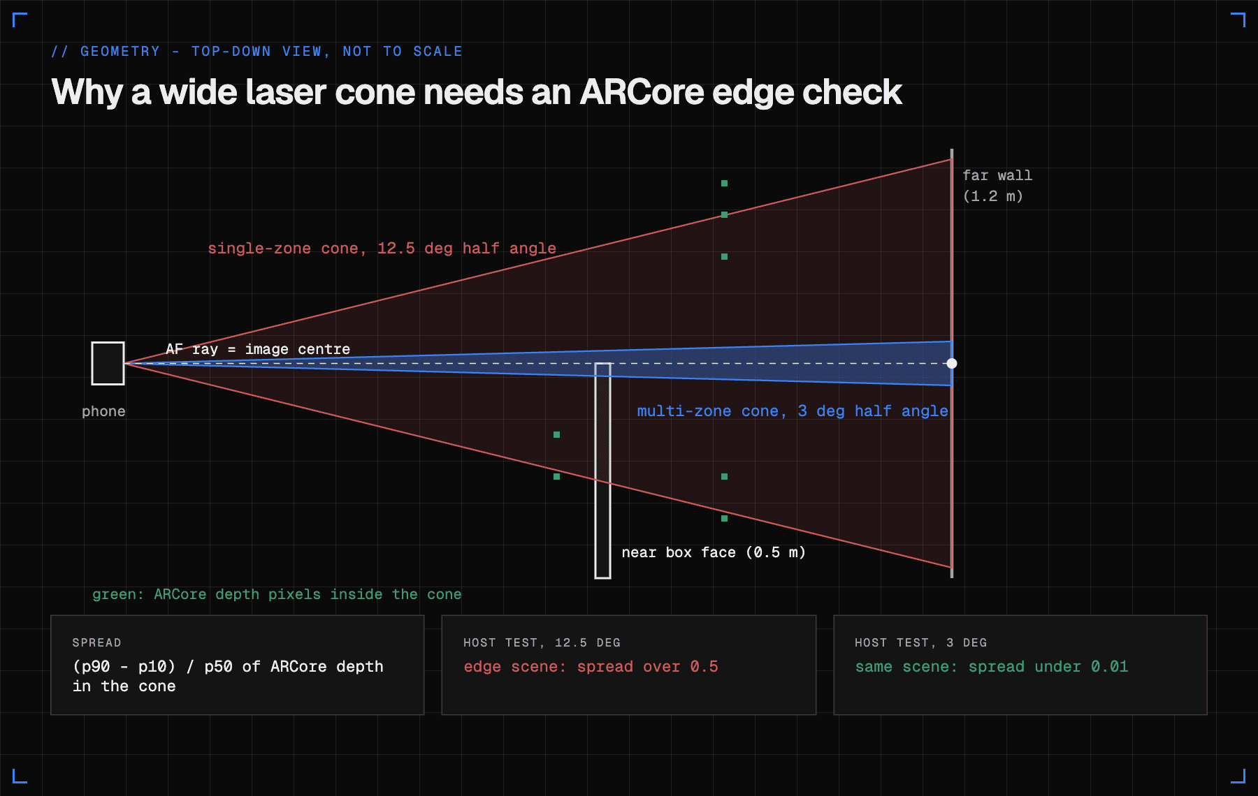
Look at the geometry image above. A single-zone emitter sees roughly a 25 degree cone. Stand in front of a box with a far wall behind it, point the center at the box edge, and the cone covers both surfaces. The sensor can blend them or lock onto the nearest. The app measures the ARCore depth spread inside that cone, the 10th to 90th percentile range divided by the median:
spread = (p90 - p10) / p50
The cone is sampled on a coarse grid inside a circle of radius tan(halfAngle) * fx pixels, with the center value taken as the median of a 5x5 patch on the AF ray. A host test builds a scene with a 0.5 m box edge on the left and a 1.2 m wall on the right, 10 px from center. With the 12.5 degree cone the test requires the spread to be above 0.5, and with the 3 degree multi-zone cone it requires under 0.01. In other words, the narrow cone does not see the edge and the wide cone does. When the spread is above the profile threshold (0.12 for single-zone), the reading is kept only if it matches ARCore depth on the AF ray within 6%, and its weight is cut to between 40% and 100% of normal.
If there is no ARCore depth to compare against, single-zone readings are accepted only right after the lens settles (moved under 2 cm and 2 degrees). That is strictWithoutDepth.
How does the C++ core fuse laser and ARCore depth?
The core is a sparse TSDF (truncated signed distance field). The idea is old and simple. Space is cut into voxels, 1 cm cubes by default, grouped into 8x8x8 blocks that are allocated only where a surface is seen (the blocks live in a hash map, and a 24,000 block cap is the roughly 150 MB budget). Each voxel stores a signed distance to the nearest surface, clamped to a band, and a weight.
For a depth measurement D along a ray, a voxel at distance z from the camera along that ray gets sdf = D - z. Positive means in front of the surface, negative means behind it. Clamp it to the truncation band and average it into the voxel with a weight. Noise in one frame averages out over many. The surface is wherever the stored value crosses zero.
Placing a laser hit in the world
Each accepted laser hit is the AF ray (the image center) at distance z, placed with the ARCore pose. A pixel (u, v) gives a direction using the camera intrinsics:
rx = (u - cx) / fx        ry = (v - cy) / fy
p_cam   = (rx * z, -ry * z, -z)        camera looks down -Z, +Y up
p_world = M * p_cam                    M = camera-to-world pose from ARCore
The code is those three lines:
void Fusion::addLaserSample(const float* M, const Intrinsics& K, float u,
                            float v, float z, const YuvImage* color,
                            float weight, float spotHalfAngle) {
  std::lock_guard<std::mutex> l(mu_);
  if (K.fx <= 0 || z <= 0) return;
  const float rx = (u - K.cx) / K.fx;
  const float ry = (v - K.cy) / K.fy;
  float wx, wy, wz;
  xform(M, rx * z, -ry * z, -z, wx, wy, wz);
  PreviewPoint p{wx, wy, wz, 255, 40, 40, 1};
  ...
The point is stored in its own list (it ends up in laser.ply) and is also splatted into the volume. A laser hit is not a perfect ray. It has a footprint, so the splat is a 5x5 bundle of rays spread over the profile's spot angle, and a visited set makes sure each voxel is counted once per hit:
const float a = spotHalfAngle > 0 ? spotHalfAngle : cfg_.laserSpotHalfAngle;
const float w = weight > 0 ? weight : cfg_.laserWeight;
std::unordered_set<uint64_t> visited;
for (int j = -2; j <= 2; ++j)
  for (int i = -2; i <= 2; ++i)
    integrateRay(M, Minv, rx + i * a * 0.5f, ry + j * a * 0.5f, z, w, color, &visited);
Weighting laser against ML depth
The weight is the whole trade-off. One ARCore depth ray adds weight 1. A laser hit adds 6 on multi-zone phones, 4 on single-zone, 1.5 on no-laser phones. The voxel update is a running weighted average:
const float t = std::min(1.0f, sdf / tr);
const float wOld = vox->weight;
const float wNew = wOld + w;
vox->tsdf = wOld <= 0 ? t : (vox->tsdf * wOld + t * w) / wNew;
vox->weight = std::min(wNew, cfg_.maxWeight);
Say a voxel has seen 4 depth rays that put the surface a few millimeters too far (t = 0.20), then one multi-zone laser hit arrives with t = 0.05. The new value is (0.20 * 4 + 0.05 * 6) / 10 = 0.11. One laser sample pulls that voxel more than half of the way toward its answer. The weight cap is 64, so very old voxels stay adaptable.
A laser hit only takes part in fusion in the "Laser + depth" and "Laser only" modes. The depth-only mode records laser hits for the log but does not fuse them.
Rejecting outliers, and calibrating scale
Outliers are rejected at three levels: the gates above for lasers, a confidence threshold of 160/255 for ARCore depth pixels (host tests check that a low-confidence image integrates zero rays and a high-confidence one integrates all 10,000), and the TSDF averaging itself.
There is one more use of the laser, and it is my favourite. ARCore's depth and tracking share one scale, but that scale is not exactly metric. The laser is. So right after the lens settles, with no edge in the cone, the app divides laser z by ARCore z on the same ray and keeps the ratio in a ring buffer of 512:
void Fusion::addScaleSample(float laserZ, float depthZ) {
  if (laserZ <= 0 || depthZ <= 0) return;
  std::lock_guard<std::mutex> l(scaleMu_);
  constexpr size_t kCap = 512;
  const float r = laserZ / depthZ;
  ...
The scale is the running median, and it locks after 20 samples with a median absolute deviation under 5%. Example: ARCore says 1.000 m and the laser says 1.030 m, so the ratio is 1.03, which would mean ARCore underestimates by 3%. The host test feeds 100 samples around 1.05 plus a 3.0 outlier and checks that the median lands within 0.005 of 1.053. Whether the real ratio on a real phone is stable enough is the part I have not measured.
There is a subtle rule that I got wrong first. Fusion stays in ARCore units: laser hits are always converted with the locked ratio (zArcore = z / lockedScale), so laser and depth surfaces land in the same place. The "Scale the model to the laser" switch only multiplies the saved model by the ratio at export, since depth and tracking share a scale and scaling the whole model is consistent where rescaling depth alone would not be.
From voxels to a mesh
The mesh is extracted with a naive surface nets pass over the sparse volume: in each 2x2x2 group of voxels where the sign of the TSDF changes, put one vertex at the average of the edge crossings, then join neighbors into quads. Winding is fixed geometrically so normals point out. Colors come from the live camera image, converted from YUV with the BT.601 formula and projected with that image's own pose, because the raw depth image usually lags the camera by a frame.
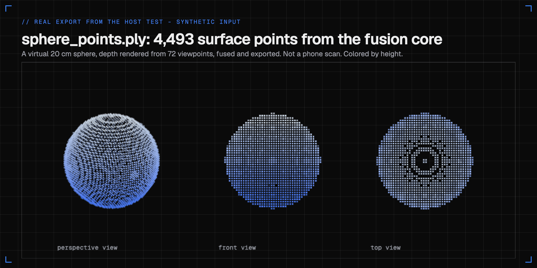
The image above is real output, but be careful what it is. It is sphere_points.ply written by the C++ host test, from a virtual sphere rendered into depth images from 72 viewpoints (3 rings of 24). It is not a phone scan. The test's numbers on that run are what the README quotes: at 1 cm voxels, 0.7 mm mean error, no non-manifold edges, and the test requires under 2% boundary edges.
How do the screens, the exports and the model viewer work?
Three tabs, one screen mounted at a time because the camera is exclusive.
Scan. Live camera with fused points on top, laser hits in red. A rangefinder readout shows the laser in mm next to the ARCore depth in mm and the difference. Modes are Laser + depth, Laser only and Depth only. Resolutions are 6 mm, 1 cm and 2 cm. The state text under the readout is the gate name, so you can see why a reading was rejected. The screen stays on while recording, and times out normally when paused.
Probe. Runs without ARCore. It shows the profile, runs the dark laser test, and reports focus-distance calibration (calibrated, approximate, uncalibrated), closest focus and hyperfocal distances, AF region support, DEPTH16 streams, and the vendor key and sensor list. Then it has the zone sweep.
Library. An orbit viewer (drag, pinch, double-tap) for meshes, clouds and laser hits, with share and delete.
Saving writes a folder with five files, in ARCore world space (meters, +Y up):
| File | Contents | Opens in |
|---|---|---|
mesh.ply | binary mesh with normals, colors, triangles | Blender, MeshLab, CloudCompare |
mesh.obj | the same mesh as text, with vertex colors | most 3D tools |
cloud.ply | colored points on the fused surface | CloudCompare |
laser.ply | every raw laser hit, in red | overlay on the mesh |
meta.json | voxel size, mode, counts, scale, device, laser kind | any editor |
In Blender, import the PLY with Y up. MeshLab opens it as-is with vertex colors. The binary layout is simple enough that I used it for the image above: a header, then 15 bytes per point (three floats and three color bytes).
The scan session behaves like this:
Saving exports while the preview keeps running; fusion pauses until the files are written. The memory budget caps the volume at about 150 MB, which the README works out to roughly 75 square meters of surface at 1 cm voxels. Past the cap, existing surfaces keep refining and new space is not added.
The typed bindings keep the JS side honest. This is the status type for the gate state, which is how the UI shows why a reading was rejected:
export type LaserState =
  | 'idle' | 'ok' | 'focusing' | 'unfocused' | 'stale' | 'disagrees'
  | 'edge' | 'unverified' | 'uncalibrated' | 'infinity'
  | 'beyond_hyperfocal' | 'too_close' | 'out_of_range'
  | 'no_metadata' | 'no_focus_key';
What did the build and the night actually look like?
A note about the history before the timeline. The first 14 commits in the repo land inside about six minutes (10:15 to 10:21). That is not me typing fast. The repo was seeded from an earlier project folder (named laserscan in a download), and I replayed its files into a clean history, one logical step per commit, with comment noise and junk files stripped. So the commit times tell you about the cleanup and the polish that followed. They do not tell you how long the first version took. The code was written before that, and I do not have a timestamped record of that part, so I will not invent one.
It was running on my Pixel 10 by about 12:17, and I have tested it by hand on that phone. I did not record measured numbers from those runs.
The Docker and Makefile workflow
I did not have a JDK, the Android SDK or the NDK on my Mac, and I did not want to install several gigabytes of toolchain into it. So everything builds in a container. The image is Node 24 on Debian, JDK 17, g++, Kotlin 2.2.0, and the Android SDK with platform 37, build-tools 37.0.0 and 36.0.0, NDK 27.1.12297006 and CMake 3.22.1.
# amd64 only: the Linux NDK and aapt2 have no arm64 builds (OrbStack runs this under Rosetta).
FROM node:24-bookworm
RUN apt-get update \
&& apt-get install -y --no-install-recommends openjdk-17-jdk-headless g++ unzip \
&& rm -rf /var/lib/apt/lists/*
It is about 4 GB. The first attempt failed because the SDK package is named platforms;android-37.0, not platforms;android-37, which sdkmanager --list told me. I also baked in build-tools 36 because Gradle was downloading it on every build. Two named volumes hold the Linux node_modules and the Gradle cache. An entrypoint reinstalls with npm ci only when package-lock.json has changed:
stamp=node_modules/.lock-sha256
sum=$(sha256sum package-lock.json | cut -d' ' -f1)
if [ "${NPM_CI:-0}" = 1 ] || [ "$(cat "$stamp" 2>/dev/null)" != "$sum" ]; then
  npm ci
  echo "$sum" > "$stamp"
fi
A full reinstall on every command adds about a minute, so I traded that for the stamp file. The one trap: if you add a dependency inside the container, your Mac's node_modules does not update. I hit that with expo-splash-screen, where a "Plugin not found" warning on the host was just a stale install.
The Makefile has no comments by design:
check: typecheck lint test

prebuild: image
	$(RUN) npx expo prebuild -p android

apk: image
	$(RUN) npm run build:apk

run:
	adb install -r $(APK)
	adb shell am start -n $(APP_ID)/.MainActivity
make check runs typecheck, lint and the C++ core tests. make apk produces the release APK. make run and make logs use adb on the host, because USB does not reach the container. A release build takes about 8 minutes in the container on my Mac, which I saw several times that morning.
The C++ core also tests natively with sanitizers, no Android needed:
g++ -std=c++17 -O2 -fsanitize=address,undefined -I../android/src/main/cpp \
  ../android/src/main/cpp/fusion.cpp test_fusion.cpp -o t && ./t
One fix is worth telling. The tests wrote their PLY output to a hardcoded scratch folder from a different machine, so they only passed on one Mac. I moved the output next to the test file, added a null check on fopen and gitignored the files. That is the commit fix(core): write test output next to the tests.
What worked, and what did not?
Worked
- Reading
LENS_FOCUS_DISTANCEthrough the normal Camera2 path with no root. Gated carefully, it is a usable single-beam rangefinder for objects at about 30-120 cm. That is the claim in the README, and it fits how the diopter error grows. - Using ARCore as the referee. The agreement band and the edge check use ARCore depth to decide whether a laser reading is believable, and the same ratio gives a metric scale.
- The sparse TSDF in C++. It is small (about 840 lines in
fusion.cpp), it passes the sphere, laser-only, scale, color, limits and cone tests under address and undefined-behavior sanitizers, and it is easy to call from Kotlin. - The release build itself. It is arm64 only, 20 MB, with only the CAMERA permission requested at runtime. The libraries pass the 16 KB page alignment check, so it loads on Android 15+ Pixels with 16 KB pages. I also ran a worst-case memory stress test on the Mac: filling the 24,000 block budget peaked at 165 to 266 MB of native memory depending on voxel size.
Did not work, or is unproven
- No raw zone grid. I cannot read the 8x8 depth image from a Pixel Pro. The README is blunt about it. Each frame gives one focus distance, blended with PDAF by the HAL.
- Diopter quantization. Past about 1.5 to 2 m the focus distance is coarse. The app rejects hits beyond 2.5 m (3.5 m on multi-zone).
- A real accuracy number. I tested it by hand on my Pixel 10, but I have not done a tape-measure comparison. The experiments I suggest in the next section are the ones I would run to get one. The only precision figure in this post is the 0.7 mm from the synthetic host test, and that measures the fusion math, not the sensors.
- Confidence-weighted depth. Weighting ARCore depth by confidence or distance would probably help, but it needs tuning on a real Pixel, so the core still weights every accepted depth ray equally.
- Probe sweeps held the camera. The first version could not be cancelled. Leaving the tab mid-sweep kept the camera for up to about 75 s on a 5x5 grid or about 3 min on 8x8, and Scan showed "camera in use". Cancel now stops it within about 0.2 s, also on tab switch or when the app goes to the background.
- The gating was wrong the first time. Reviewing the math I found four bugs: uncalibrated focus values were being used as distances, laser hits were converted to ARCore units only when the scale toggle was on, the agreement bands ignored ARCore's bias, and moving along the AF ray without a refocus was not caught. All four are fixed, and the fixes compile and build. I have not A/B tested them against scans.
I also did a search for prior work, because I wanted to know whether I was reinventing something. Using LENS_FOCUS_DISTANCE to put neural depth on a metric scale has been done before, so that part is not new. I found nothing that combines these pieces: fusing Pixel laser ranges as weighted voxel measurements with ARCore raw depth, per-laser-type gates with an edge check from ARCore depth inside the cone, and the dark-exposure test that separates single-zone from multi-zone without root. My search had limits (a handful of web queries), so the fair claim is a new combination, not a first.
How would I check how good it really is?
These are experiments from my own list, not results:
- Tape check. Point at a wall from 0.3, 0.5, 1.0 and 1.5 m, measured with a tape. Compare the laser number, the ARCore line and the tape. The laser error should grow roughly with z squared, and ARCore should show a steady percentage offset.
- Scale. Scan a box of known size twice, with "Scale the model to the laser" off and on. Measure both in MeshLab.
- Mode comparison. Scan one flat wall in Depth only and in Laser + depth, fit a plane in CloudCompare and compare the RMS error.
- Edge gate. Aim at a table edge with the floor far behind it. A single-zone phone should show
edge, a multi-zone phone mostly should not. - Stale gate. Lock on a wall at 1 m and step slowly forward. It should flip to
staleafter about 3 cm unless the lens refocuses.
If you scan with it, the tips from the README apply: objects at 30-120 cm, good light, textured surfaces (ARCore needs features and the laser AF needs contrast to confirm focus), and move slowly. Pause for about a second where you want laser hits, since each pause lets the lens settle. In laser-only mode, expect a sparse trail of red hits, a few per second, not a dense cloud.
If you want a different kind of on-device engineering story, I wrote about shipping React Native updates without the store in BDUI OTA for React Native, and about squeezing a real-time audio path on a Mac in TapTalk, Orukeet and Silero VAD on Core ML.
FAQ
Can a phone's laser autofocus work as a LiDAR?
Roughly, as a hand-swept single beam. LaserScan reads the laser-driven focus distance on Google Pixels, checks it against ARCore depth and fuses both into a 3D model. It is a fun experiment, not a precision tool.
How do you read a Pixel's laser autofocus without root?
Android hides the sensor's zone grid, but three signals are reachable: the LENS_FOCUS_DISTANCE value in every frame's metadata (z = 1 / diopters), vendor camera keys, and ARCore raw depth.
How accurate is LaserScan?
The C++ fusion core reconstructs a synthetic 20 cm sphere with 0.7 mm mean error in host tests. I tested it by hand on a Pixel 10, but there are no tape-measure numbers yet, so that figure measures the math, not the sensor.
What file formats does LaserScan export?
mesh.ply, mesh.obj, cloud.ply and laser.ply.
A phone's laser autofocus is reachable without root, but only as a lens position: z = 1 / diopters at the AF point, one value per frame, blended with PDAF by the camera HAL. That is enough for a gated, hand-swept single-beam range finder if you check every reading against something else (here, ARCore raw depth) and throw away stale, edge, out-of-range and uncalibrated values. Fusing the survivors in a sparse TSDF with a weight of 6 against 1 for a depth ray gives meshes and clouds you can open in Blender. What I have is a working pipeline, 0.7 mm mean error on a synthetic sphere, and no real-world accuracy figure. LaserScan is a fun night project, not a precision tool.
References
- vakharwalad23/pixel-laserscan on GitHub (source, README, v0.1.0 release)
- ST VL53L8CX datasheet (8x8 multizone, 940 nm VCSEL, 65 degree diagonal field of view)
- Android Camera2 CameraMetadata reference (focus distance calibration values)
- Android CaptureResult.LENS_FOCUS_DISTANCE
- ARCore Raw Depth codelab
- OnePlus Laser Tool on F-Droid (a laser-sensor tape measure on OnePlus phones)
- HybridDepth (focus plus single-image depth for metric depth)